
I. IN BRIEF
This section is a brief summary to help you quickly access the key information you need. If you want to dive deeper into the details, simply continue with the rest of the course.
Doing your weight and balance analysis is mandatory under the regulations, but it also helps you operate safely within the limits defined by the manufacturer. In addition, it gives you a clear overview of how the aircraft will behave in flight.
To understand how weight and balance affect your aircraft’s handling, refer to the article "Weight and Balance Effects on Light Aircraft Handling".
I.1 Some definitions
Centre of Gravity (CG): The single point where the aircraft’s total weight is considered to act. It determines the aircraft’s balance and stability and must remain within approved limits for safe flight.
Arm: The horizontal distance between a reference point (also called the datum) and the location where a load is applied. Expressed in meters or inches. Arm × Weight = Moment.
Moment: The turning force produced by a weight acting at a given arm. It represents how strongly a load tries to pitch the aircraft nose up or nose down. Calculated as: Moment = Weight × Arm.
In your flight preparation, determine the extra load you can still accept in case of last-minute changes.
Normally, you take the day’s conditions and your actual weight to calculate takeoff and landing distances, then compare them with the declared distances of the runways you plan to use. By taking the reverse approach = starting from the performance you will need (with an appropriate safety margin) and combining it with the day’s conditions, you obtain the Maximum permissible takeoff weight or "regulated takeoff weight". Compare this with your actual ramp weight: the delta is what you can still accept at the last minute, provided CG limits are respected. This may be a heavier suitcase or an unexpected passenger. This method is common among professional pilots. It adds some time to the preparation, but avoids having to redo all your calculations or refuse someone if a last-minute change occurs. Use it whenever baggage, passenger load, or fuel quantity are not fully known before arriving at the aeroclub.
II. General rules
II.1 Stay Safe
According to the Air OPS regulation, during any phase of operation, the loading, mass, and centre of gravity (CG) position of the aircraft must comply with all limitations specified in the AFM or equivalent document. (NCO.POL.100)
For your safety, the regulations require that:
-
- The aircraft’s mass and centre-of-gravity position allow the flight to be conducted within the limits defined in the airworthiness documentation.
- All equipment, baggage, and cargo are correctly loaded and secured, and an emergency evacuation must remain possible at all times.
- The aircraft operating limitations specified in the Aircraft Flight Manual (AFM) are never exceeded during any phase of the flight.
II.2 Mass
The aircraft’s mass is computed by adding all elements that will be on board (empty aircraft mass, passengers, fuel, equipment, baggage, etc.).
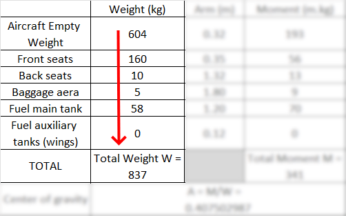
This total mass must remain below the maximum limits defined by the manufacturer.
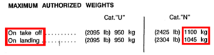
For light aircraft, the most common limits are the Maximum Takeoff Weight (MTOW) and Maximum Landing Weight (MLW). Larger aircraft may also have additional limits such as Maximum Taxi Weight (MTW) and Maximum Zero Fuel Weight (MZFW).
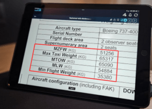
Being below the certified mass limits does not guarantee safe performance. Always ensure the aircraft can meet the required takeoff, landing, and in-flight performance for the day’s weather, runway conditions, and obstacle clearance.
Mass vs Weight:
In physics, mass (kg) and weight (a force, in Newtons) are different concepts.
However, in aviation, both terms are commonly used interchangeably to refer to the aircraft’s mass, and both are expressed in kilograms in everyday practice.
You can use a small portable handheld luggage scale (check Amazon) to weigh your baggage accurately!
II.3 Center of Gravity (Balance)
It is essential to remain within the CG envelope provided in your Flight Manual or Weight & Balance sheet.
Whether the aircraft is forward-loaded or aft-loaded will significantly affect its behaviour in flight.
CG location influences:
-
- the effort required during rotation,
- pitch stability,
- control authority,
- and even fuel consumption.
Flying outside the approved CG range can severely compromise safety and controllability.
III. Type of Diagrams
Manufacturers provide different types of mathematical tools to help you determine the aircraft’s balance (i.e. the centre of gravity location).
III.1 Table
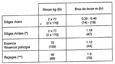
The most common tool for performing weight and balance is the loading table linked to the Weight and Balance Envelope. The manufacturer provides both the general loading table and the CG envelope.
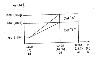
The CG envelope (or center of gravity envelope) is a graphical representation of the acceptable combinations of aircraft weight and center of gravity location.
It defines:
-
- The maximum and minimum weight limits
- The forward and aft CG limits
- Sometimes different zones for different flight categories (e.g., Utility vs. Normal)
To obtain the correct figures for your specific aircraft, always refer to the latest Weight and Balance Report, which includes the updated empty mass, moment, and equipment weights.
Let’s take this fictitious example. You can see that the empty weight is already included, as provided by the maintenance shop from the latest weighing.
This method is quite simple:
-
- Step 1: Enter all the masses into the table.
Watch out: if fuel is given in volume, convert it to mass.
Example: 40 L of 100LL gives 28.8 kg (using the 0.72 factor).
-
- Step 2: Multiply each mass by its corresponding arm to obtain the individual moments.
- Step 3: Add all masses and all moments at the bottom of the table to get the totals.
- Step 4: Divide the total moment by the total mass to obtain the mean arm — this corresponds to the CG location.
Important: The final arm is not the sum of all individual arms. It is the total moment divided by the total weight.
-
- Step 5: Plot your values onto the loading diagram (envelope).
AVGAS 100LL: 1 L ≈ 0.72 kg (1.6 lb) | 1 US gal ≈ 2.72 kg (6.0 lb)
JET A-1: 1 L ≈ 0.80 kg (1.8 lb) | 1 US gal ≈ 3.03 kg (6.7 lb)
| Forward CG |
Aft CG |
| More stable |
Less stable |
| More drag | Less drag |
| Higher stall speed | Lower stall speed |
| Longer takeoff roll | Shorter takeoff roll |
| Harder rotation & flare | Risk of over-rotation |
| Less fuel efficient | More fuel efficient |
To understand how weight and balance affect your aircraft’s handling, refer to the article Weight and Balance Effects on Light Aircraft Handling.
See our ICARUS Toolbox – Aviation Conversion Table
Units may differ from one manufacturer to another. Always double-check that you are using consistent units before performing any calculation. Below, note the difference in units used on this Piper PA-44.
Example:
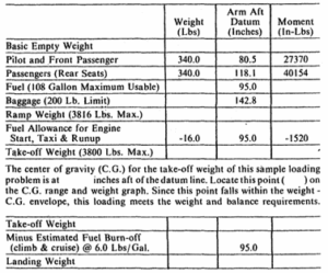
Note the different units used here.
Remove the taxi and trip fuel to get an idea of your mass and balance at landing. Will you still be within the envelope?
Some aircraft tend to be forward-CG machines, and depending on where your passengers sit, you could even move out of the forward limit. That’s why we also recommend plotting the landing point (mass × moment, recalculated) to visualise your CG position upon arrival, as well as the zero-fuel weight. This lets you see how your CG and mass will change if you burn more fuel than expected, for example during a diversion to your alternate, or in any situation where fuel consumption ends up significantly higher.
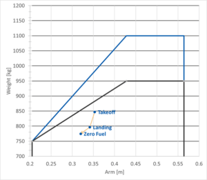
The black envelope corresponds to operating the aircraft in the Utility category, while the blue envelope represents the Normal category. The Normal category is more permissive in terms of weight and CG range, but it allows fewer manoeuvres and imposes more restrictions on in-flight handling.
See the explanation at the end of the article for more details.
Also make sure to comply with any limitations related to the baggage area.
Even if you are within the weight and balance envelope, this does not guarantee that you will meet the required takeoff or landing performance for the available runway length, nor that you will clear obstacles with sufficient margin or achieve an adequate climb rate. The performance assessment is just as critical when deciding whether the flight can be conducted safely.
III.1.1 Explanation: Category U (Utility) and Category N (Normal)
These categories come from the aircraft certification rules:
Category N – Normal:
This is the standard operating category. It allows all normal flight operations but excludes aerobatics. Only gentle maneuvers and standard bank angles are permitted.
Category U – Utility:
This category allows more demanding maneuvers, including limited aerobatics (such as chandelles and lazy eights), provided the aircraft is within the Utility weight and CG sub-envelope.
The permitted maneuvering load factors are higher in Utility category.
If your loading point falls inside the Utility envelope, you may fly in the Utility category.
If it only fits in the Normal envelope, you must operate under Normal-category limitations.
Example:
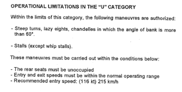
Here is an example of what you might find in the Flight Manual of a four-seat, single-engine piston aircraft. Check your own Flight Manual to know exactly what manoeuvres are permitted in the Utility category for your aircraft.
Operating outside the envelope (too far forward, too far aft, or overweight) can lead to:
-
- Reduced stability or controllability
- Stall risk
- Structural overload
III.2 Diagram
You may also encounter this type of diagram. Simply follow the dotted example to complete the weight and balance calculation. No multiplication is required to find the arm, you only need to add up all the masses at the end. See the step-by-step instructions for filling out the diagram in the continuation of the article.
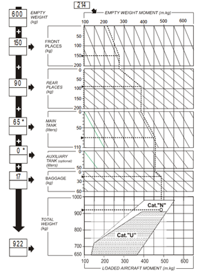
How to Use This Type of Loading Diagram
-
- Step 1: Enter the mass of each item in the boxes on the left.
- Step 2: Start at the top by taking the aircraft’s empty-weight moment.
- Step 3: Move downward, following the diagonal lines in parallel (see the dotted example), until you reach the intersection with the mass line of the next item (e.g. front seats).
- Step 4: From that intersection, move straight down vertically. When you reach the lower part of the diagram, follow the diagonal lines again until you reach the intersection with the next item’s mass.
Continue this process for all remaining items.
-
- Step 5: When you reach the envelope, move straight down vertically — this gives you the loaded aircraft moment. Then intersect it with your aircraft’s total mass on the vertical scale.
- Step 6: Read the diagram and check whether your loading point is within the envelope
If the aircraft documentation does not provide approved data for the holding regime, the pilot should derive the fuel flow data from the long-range/best-range cruise data or, if this is not provided, from the lowest available cruise data in power setting tables.
You may legally take off with a higher mass than your Maximum Landing Weight (MLW).
Just make sure you burn enough fuel before landing — except in an emergency, of course.
III.3 Load and trim sheet
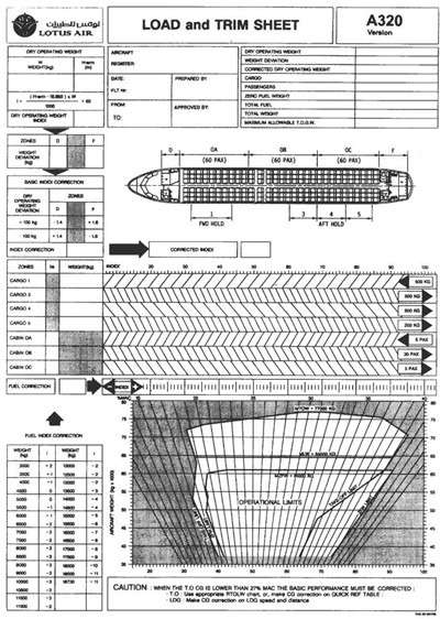
This type of diagram is not commonly used on light aircraft.
Refer to articles: "Understanding Operational Weights: MATOW, TOW, LDW",and "ZFW and How to Determine MATOW and Maximum Payload".
IV. References
NCO.POL.100 (EU Reg. 923/2012)